1. First, Determine: Does Your Application Need M51?
M51 is not a universal upgrade that is “better than M42 across the board.” The core difference lies in red hardness—the ability of the tooth tip to retain hardness at elevated temperatures. Comparative analysis from SawbladeUniversity indicates that M42 tooth tips begin losing hardness around 600°C, while M51 extends this temperature window upward. Only when cutting conditions actually push the tooth tip into that temperature range does higher cobalt content translate into a service-life advantage.
Application Signals That Favor M51
| Application Signal | Why M51 Is a Better Match |
|---|---|
| Frequent cutting of austenitic stainless steel (304 / 316, etc.) | Stainless steel work-hardens and conducts heat poorly, pushing more heat into the tooth tip rather than carrying it away with chips; M51’s red hardness directly corresponds to tooth-tip resistance to softening |
| Cutting high-alloy steels, tool steels, and difficult-to-machine alloys in the 45–50 HRC range | M51 tooth material covers a higher hardness ceiling than M42; M42 is typically recommended up to ~45 HRC, while M51 can reach ~50 HRC (confirm with supplier test data) |
| Large-section solid stock with long single-cut times and pronounced heat accumulation | Large cross-sections keep the tooth tip in the cutting zone for extended periods, increasing sustained thermal load; insufficient red hardness accelerates tooth-tip rounding |
| Production sawing pursuing high surface speed for throughput | Higher surface speed raises tooth-tip temperature; M51’s high-temperature hardness retention supports stable cutting under the same machine conditions |
| M42 tooth failure mode is “rounding / edge collapse” rather than “tooth breakage” | Rounding is a classic signal of thermal softening, indicating red hardness has become the limiting factor; breakage is more likely related to impact, improper feed, or pitch selection |
Signals That Do Not Require M51
-
Cutting low-carbon steel or ordinary structural steel at conventional shop-floor speeds (par ex., 150–250 sfpm), where tooth-tip temperature is far below the softening threshold—M42 delivers equivalent performance.
-
Failure dominated by tooth breakage or stripping rather than rounding. Higher-cobalt alloys typically trade some toughness for red hardness; under impact loads, M42’s fracture resistance may actually be more favorable.
-
Cutting thin-wall tube or small-section profiles, where per-tooth contact time is short and heat accumulation is limited—M51’s red-hardness premium is difficult to recover.
2. Application Selection Table: Material × Hardness × Cross-Section × Pitch
The following selection tables use number of teeth in cut simultaneously as the core constraint. The general rule for band saw blade pitch selection is to maintain approximately 3–24 teeth in cut at any given time; use fine pitch for thin-wall / small cross-sections, coarse pitch for large-section solid stock, and variable pitch (par ex., 4/6, 5/8) to cover most shop-floor applications.
Solid Bar / Square Stock
| Cross-Section (diameter or width) | Recommended Variable Pitch (TPI) | M51 Applicability Notes |
|---|---|---|
| ≤ 25 mm | 10/14 | Limited thermal load on small cross-sections; if cutting stainless and M42 rounds quickly, evaluate M51 at this pitch |
| 25–50 mm | 6/10 or 5/8 | Typical starting range for M51, balancing chip evacuation and red hardness |
| 50–80 mm | 5/8 or 4/6 | Medium-to-large cross-sections in stainless / high-alloy steel; M51 advantage becomes evident |
| 80–120 mm | 4/6 or 3/4 | Sustained thermal load rises; red hardness is the key variable |
| 120–200 mm | 3/4 or 2/3 | Large-section solid stock; M51 counters heat accumulation from prolonged cutting |
| 200–400 mm | 2/3 or 1.4/2 | For large cross-sections plus difficult-to-machine materials, M51 is the more suitable tooth material |
Tube / Profile (by Wall Thickness)
| Wall Thickness | Recommended Variable Pitch (TPI) | Notes |
|---|---|---|
| < 2 mm | 14/18 or 10/14 | Thin wall requires fine pitch to prevent tooth snagging; M51’s red hardness is usually not the primary variable in such applications |
| 2–3 mm | 10/14 | Balances tooth count and chip evacuation |
| 3–5 mm | 8/12 or 6/10 | Medium wall thickness |
| 5–8 mm | 6/10 or 5/8 | Cutting heat begins to rise; consider M51 for stainless tube bundles |
| 8–12 mm | 5/8 or 4/6 | Heavy-wall tube; M51 red-hardness benefit increases |
| > 12 mm | 4/6 or 3/4 | Approaches solid-stock thermal load |
Machine Parameter Coordination: Surface Speed and Feed
Once pitch is selected, surface speed is the second operational variable determining tooth-tip temperature. M51’s red-hardness advantage is only fully realized at higher surface speeds; if surface speed remains low, the gap between M51 and M42 narrows.
| Material | Typical Surface Speed Range (m/min) | Relationship to M51 |
|---|---|---|
| Low-carbon / structural steel | 60–80 | M42 is usually sufficient at conventional speeds; M51 for production speed-up scenarios |
| Medium-carbon / alloy steel | 40–60 | M51 enters its match zone at medium-to-high alloy content |
| Tool steel / bearing steel | 30–40 | Higher hardness; M51 tooth-material hardness ceiling provides margin |
| Stainless steel (austenitic) | 25–40 | Core application zone for M51; low thermal conductivity concentrates heat at the tooth tip |
Surface speed ranges are conventional reference values for bimetal band saw blades; confirm against machine capability and actual workpiece testing. Start initial feed at a lower value, observe chip morphology and tooth-tip condition, then adjust gradually.
3. M51 vs. M42: Tooth Material Differences, Cost, and Decision Boundary
| Dimension | M42 Bimetal Tooth | M51 Bimetal Tooth |
|---|---|---|
| Cobalt content (representative) | ~8% | ~10%, often with vanadium for carbide refinement |
| Tooth-tip hardness (typical) | ~67–69 HRC | ~69–70 HRC |
| Red-hardness positioning | General shop-floor applications | Sustained high-temperature / difficult-to-machine applications |
| Typical hardness coverage | Up to ~45 HRC | Up to ~50 HRC (confirm with supplier test data) |
| Toughness tendency | Relatively more resistant to impact breakage | Improved red hardness; impact applications require attention to pitch and feed matching |
| Relative cost | Baseline | Typically 15%–30% premium |
Economic decision framework: Whether M51’s premium is justified depends on whether the service-life gain covers the price difference. An operational criterion: if under the same application M42 fails after X cuts due to tooth-tip rounding, and M51 sustains approximately 1.3–1.6× or more cuts, the upgrade is cost-justified; otherwise, prioritize checking pitch, surface speed, feed, and coolant rather than switching to a higher-cobalt tooth material. “Should I use M51” should be answered by measured service-life data, not by grade labels.
4. Specification Coverage: Standard Dimensions and Pitch Options
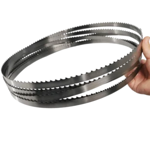
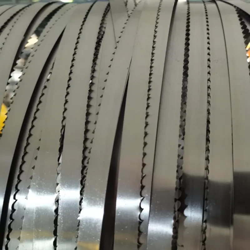
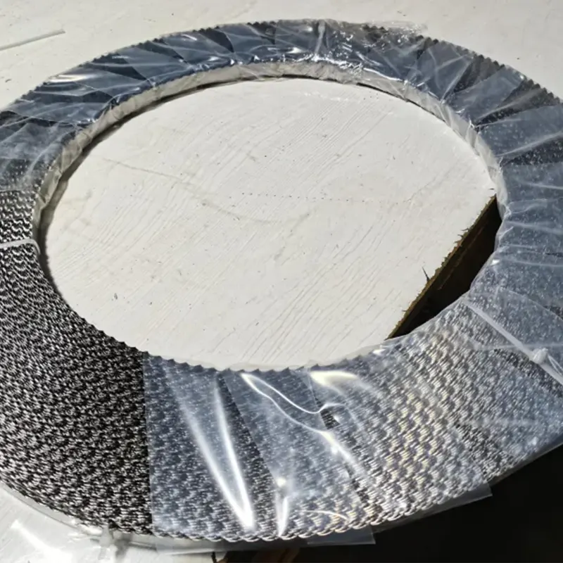
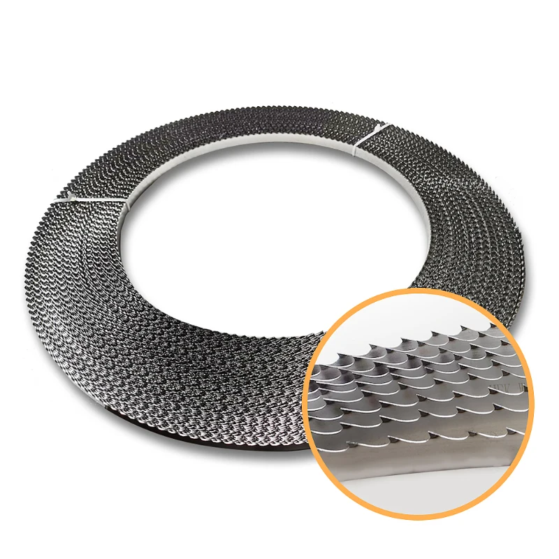
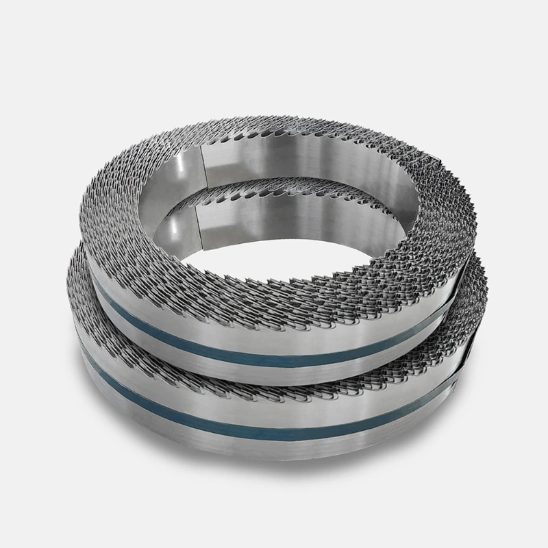
M51 bimetal band saw blades commonly cover widths from 13 mm to 80 mm, with thickness increasing as width increases. Below are representative dimensions and variable pitch ranges; specific lengths are customized to machine models, available in welded loops or coils.
| Width × Thickness (mm) | Typical Variable Pitch (TPI) |
|---|---|
| 13 × 0.65 / 13 × 0.90 | 6/10, 8/12, 10/14 |
| 20 × 0.90 | 4/6, 5/8, 6/10, 8/12, 10/14 |
| 27 × 0.90 | 4/6, 5/8, 6/10, 8/12, 10/14 (coarse-pitch scenarios also 2/3, 3/4) |
| 34 × 1.10 | 4/6, 5/8, 6/10, 8/12 (coarse-pitch scenarios also 2/3, 3/4) |
| 41 × 1.30 | 4/6, 5/8, 6/10 (coarse-pitch scenarios also 1.4/2, 2/3, 3/4) |
| 54 × 1.60 / 67 × 1.60 / 80 × 1.60 | 1.4/2, 2/3, 3/4, 4/6 |
Dimension and pitch combinations reference publicly available M51 bimetal band saw blade specification data. 34 × 1.10 × 3/4 TPI × 4720 mm is a common specification combination among welded-loop blades, suitable for medium-sized automatic / semi-automatic band saw machines; at the same dimensions, the difference between M51 and M42 lies in tooth-material red hardness, not in the geometric specification itself. Final pitch selection should return to the cross-section and wall-thickness tables in Section 2, confirmed against the machine’s allowable surface speed and feed capability.
5. FAQ
What materials are M51 bimetal band saw blades suitable for?
M51 is particularly suited to materials and applications where the tooth tip generates sustained high heat during cutting: austenitic stainless steel (304 / 316, etc.), high-alloy steels, tool steels, and difficult-to-machine materials in the 45–50 HRC range; large-section solid stock and high-surface-speed production sawing are also matching scenarios for M51. Low-carbon steel at conventional speeds, thin-wall small cross-sections, and impact applications where breakage is the primary failure mode typically do not require upgrading to M51.
How much longer does M51 last compared to M42?
There is no fixed multiplier. M51’s service-life advantage depends on whether the application actually generates sustained tooth-tip high heat. A representative reference: when M42 fails after a certain number of cuts due to tooth-tip rounding, if M51 increases the cut count to approximately 1.3–1.6× under the same application, the premium begins to be recovered; below this range, prioritize investigating pitch, surface speed, feed, and coolant rather than attributing it to tooth-material grade. Actual service life must be based on measured data with workpiece material, cross-section, machine parameters, and cooling conditions as variables.
What cross-section is a 34 × 1.10 × 3/4 TPI × 4720 mm M51 blade suitable for?
3/4 TPI variable pitch in solid-stock selection typically corresponds to a cross-section range of approximately 80–200 mm; in tube / profile scenarios, 3/4 TPI leans toward heavy-wall or large cross-section bundles. 34 mm width × 1.10 mm thickness is a common blade specification for medium-sized band saw machines, and 4720 mm length is customized to the specific machine. If the actual workpiece cross-section is below 50 mm or wall thickness below 5 mm, 3/4 TPI may be too coarse—return to the cross-section selection table and reduce pitch.
What surface speed and pitch should be used for M51 blades cutting stainless steel?
The typical surface speed reference range for austenitic stainless steel is 25–40 m/min. Select pitch by cross-section / wall thickness: 25–50 mm solid stock starts at 6/10 or 5/8 TPI, 50–80 mm uses 5/8 or 4/6 TPI, and thin-wall tube (< 2 mm) uses 14/18 or 10/14 TPI. M51’s red-hardness advantage is more pronounced at higher surface speeds, but initial feed should start at a lower value to avoid impact loading before the tooth tip has been run in.
Do M51 blades require special machine parameters?
No “special parameters” are required, but parameter matching is necessary. M51’s red-hardness advantage is realized when tooth-tip temperature is elevated; if the machine always runs at low speed and low feed, the tooth-tip temperature does not reach the range where red-hardness differences are sensitive, and M51 and M42 performance converges. The key is aligning surface speed, feed rate, and pitch to the actual cross-section and material, rather than simply changing tooth-material grade.